
A Picture is Worth a Thousand Words:
Demystifying the Shear Force and Bending Moment Diagrams
By Ahmet Zeytinci, P.E., F-NSPE

It is no secret that I received all my degrees from Istanbul Technical University (ITU), founded in 1773. ITU is one of the premier engineering schools in Europe, and back in the early 1970s, we had about 150 full-time faculty members and support staff in our Civil Engineering department. For my doctoral research, I was working on a highly mathematical problem on vibrations of plates and one of my Ph.D. advisors was a professor who worked with the well-known scientist Richard Edler von Mises at Harvard University while completing his PhD. Some of my readers may also remember von Mises who defined the yield criterion that suggests that the yielding of materials begins when the second deviatoric stress invariant J2 reaches a critical value. As I reflect on my 40-year career in structural engineering, it is remarkable to see how the landscape has changed, while some knowledge and educational tools that I learned from my mentors are priceless and I use them in my classes every day. Today we will focus on shear force (V) and bending moment (M) diagrams. Many students struggle when they try to draw their first shear and moment diagrams.
In structural engineering, we are interested in the analysis and design of beams or structural members supporting concentrated and/or distributed loads that are mostly perpendicular to the axis of the members. In practice, beams are usually long, straight, and prismatic and such transverse loadings would cause only bending and shear forces. When the loads are not perpendicular to the member, they also produce axial forces as well. The concentrated loads may be expressed in newtons (N), pounds (lb), or their multiples, kilonewtons (kN) or kips. Distributed loads are generally expressed in N/m, kN/m, lb/ft or kips/ft. A shear force diagram (V) is a graph in which the abscissa (horizontal reference axis) represents distances along the beam length, and the ordinates (vertical measurements) represent the transverse shear at the corresponding beam section. A moment diagram (M) is a graph in which the abscissa represents distances along the beam and the ordinates represent the bending moment at the corresponding sections. Shear and moment diagrams can be drawn by calculating values of shear and moment at various sections along the beam and plotting enough points to obtain a smooth curve. Such a procedure is rather impractical and time consuming.
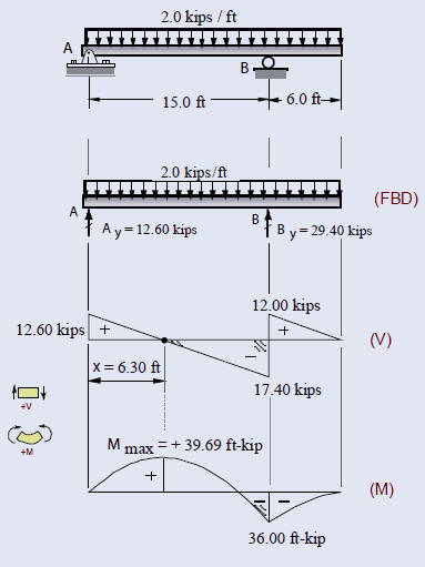
Right at this point, I remember my Ph.D. advisor’s words, “A well-drawn (V) and (M) diagram is like ‘poetry’ for some of us and you have to feel them without doing any number crunching.” My colleague Vagelis did just that for our readers and prepared a dozen beautiful diagrams using his well-known software, Beam-2D as shown in the Problem Section this month.
For the sign conventions, positive moment generates a curvature that tends to hold water (concave-upward curvature) or moment creating tension in bottom fibers of beam, whereas negative moment causes curvature that sheds water (concave-downward curvature). For the sign of shear, positive shear is the upward shear to left. This is a standardized and universally accepted convention. Because the convention is related to the probable deflected shape of the beam for a prescribed loading condition, it may be helpful to intuitively sketch the beam’s deflected shape to help in determining the appropriate signs. With the aid of such diagrams, the magnitudes and locations of various important quantities like Mmax become immediately apparent. The maximum moment Mmax occurs at places where shear = 0 or V changes sign. It is convenient to draw these diagrams directly below the free-body diagram of the beam using the same horizontal scale. Why these diagrams are so important? Because by using these diagrams, an engineer can see, at a glance, the performance requirements of a structural member at every section.
Finally, we have to remind our readers that FE and PE are very fast-paced exams and you will have little time to look up information. Therefore, make sure you are familiar with your reference material and begin with the subject areas you know best. This will give you more time and build your confidence.
Most importantly, stay relaxed and confident. Always keep a good attitude and remind yourself that you are going to do your best!
Until next time,
Ahmet Zeytinci, P.E.
This email address is being protected from spambots. You need JavaScript enabled to view it.
